Stk413-430 Circuit Diagram ~upd~ Guide
A typical application circuit for the STK413-430 includes several essential blocks to ensure stable operation:
) forms a low-pass filter to keep ultrasonic noise out of the amplification stage. 3. Negative Feedback Loop (NFB) stk413-430 circuit diagram
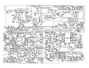
Direct outputs for the three amplified channels. Typical Application Circuit Diagram A typical application circuit for the STK413-430 includes
This article provides a comprehensive guide to the STK413-430. It serves as a resource for electronics enthusiasts and technicians, covering its key specifications, practical applications, a sample circuit diagram, and crucial design considerations. covering its key specifications